|
 
|
|

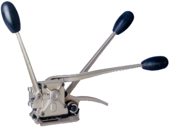
ZL31
OPERATION MANUAL
SAFETY INSTRUCTIONS
Please read these instructions carefully. Failure to follow
these instructions could result in severe injury.
| 1. |
Before using the tool, read
the entire operation manual thoroughly. |
| 2. |
Always wear safety glasses
and face protection when operating the tool. |
| 3. |
Always wear protective gloves
when handling strapping. |
| 4. |
Always use only replacement
parts from an authorized dealer. replacement
parts from an authorized dealer. |
| |
These tools are designed for use with high tensile strapping
and all parts are manufactured or treated for these extreme
conditions. Performance of your tool will be affected
if any other parts are used, which may cause injury. |
SPECIFICATIONS
| Weight: |
11
lbs. (5 kg) |
| Base
Length: |
4.2"
(105 mm) |
| Base
Width: |
2.4"
(60 mm) |
| Height: |
4.2" (105 mm) |
Strapping Qualities:
Designed for use with regular duty strapping (107,000
psi / 750 N / mm2) to high tensile strapping
(156,000 psi / 1100 N / mm2). |
| Model Number |
Strap Width |
Strap Thickness |
| ZL31-1 |
3/4" (19mm) |
.025"-.031" (0.635 mm - 0.80 mm) |
This tool is not designed to be used with strapping
below .025" (0.635 mm) thickness or above .031"
(0.80mm) thickness. |
Top of page
OPERATING
INSTRUCTIONS
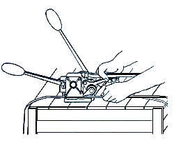
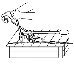
| A
Place strapping tightly around the package and hold
in place with left hand. Make sure lever ZL is in fully
open position as shown in diagram.
Take tool with right hand and pull the feedwheel lever
towards the sealing lever.
Insert both portions of the strap with left hand into
the sealing section.
Release the feedwheel lever and make certain strapping
is held by strap guide.
|
|
|
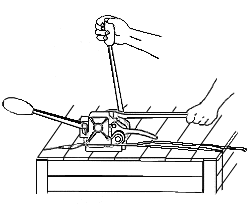
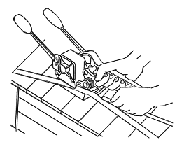
B
Hold tool firmly with left hand on the sealing lever.
With right hand move the tension lever forward and
backward until the desired tension is obtained.
|
|
|
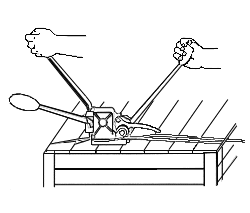
C
Place right hand firmly on the tension lever for supporting
the tool.
With left hand push the sealing lever forward until
it reaches the stop.
|
|
|
D
Move the sealing lever back to its original position.
Place right hand firmly on the tension lever for supporting
the tool.
With left hand pull lever ZL towards you until it reaches
the stop.
|
|
|
E
Move lever ZL back to fully open position as shown
in diagram.
To release the tool, with right hand pull the feedwheel
lever towards the sealing lever, pushing the lever to
the left away from the sealing section.
|
|
Top of page
MAINTENANCE
Clean
the sealing section regularly with compressed air to remove
any dust and particles.
Lubricate the die (position 18), punch (position 36) and punch
ZL (position 31) daily with a thin grade of oil.
This will reduce friction and extend the life of the tool
as well as the parts.
Spray the entire tool daily with a rust preventative, this
will prevent any rust formation.
Top of page
ADJUSTMENTS
TO
ADJUST SEALING DEPTH
Loosen nut (position 42), adjust hexagon socket set screw
(position 59) with a hexagon key, turn counter clockwise to
increase sealing depth, or turn clockwise to decrease sealing
depth, retighten nut.
TO
ADJUST CLEARANCE BETWEEN THE FEEDWHEEL (POSITION 5) AND GRIPPER
(POSITION 37)
The clearance between the feedwheel and the gripper should
be .020" (.51 mm). If the clearance is more or less than
this, it must be adjusted.
To reduce the clearance: loosen nut (position 42A),
turn hexagon socket set screw (position 41) counter clockwise
with a ball hexagon key, retighten nut.
To increase the clearance: loosen nut (position 42A),
turn hexagon socket set screw (position 41) clockwise with
a ball hexagon key, retighten nut.
TO ADJUST SEALING DEPTH FOR LEVER ZL (POSITION 25)
Loosen nut (position 27), adjust hexagon socket screw (position
26) with a hexagon key, turn counter clockwise to increase
sealing depth, or turn clockwise to decrease sealing depth,
retighten nut.
Top of page
REPLACEMENT
OF PARTS
Note: If you are not familiar with the following replacement
procedures, please contact your authorized dealer
for a demonstration or for service.
To Replace The Feedwheel (Position 5)
| 1. |
Remove external retaining
ring (position 3). |
| 2. |
Remove tensioning assembly
(consisting of tension lever (position 11) and feedwheel
shaft (position 2)). |
| 3. |
Install new feedwheel with
the "O" and "I" marking facing the
strap guide (position 4), reinstall tensioning assembly
observing the key way position during assembly. |
| 4. |
Reposition strap guide onto
the protruding feedwheel shaft. |
| 5. |
Reinstall external
retaining ring. |
To Replace The Gripper (Position 37)
Note: The gripper is held in a nonadjustable
position with spring tension pin (position 38).
| 1. |
To remove
gripper, use drift pin matching the dimension of the spring
tension pin (position 38) and drive the spring tension
pin into the tool base, until the gripper comes loose
from its position. |
| 2. |
Lift feedwheel lever (position
7) to access gripper. |
| 3. |
Clean cavity area and add one
drop of a thin grade of oil in the cavity. |
| 4. |
To install new gripper, place
the gripper into the cavity of the tool base. Reinstall
the spring tension pin and drive it into the hole of the
tool base, until it is flush with the tool base. |
To Replace The Knife (Position 19)
| 1. |
Remove housing cover ZL (position
66), by removing 3 hexagon socket shoulder screws (position
64) and 1 hexagon socket shoulder screw (position 63).
Important: This screw in position 63 must be reinstalled
in this exact position (lower left hand corner) as it
is shorter. It must also sit flush against the housing
cover ZL when reinstalled. |
| 2. |
With pliers, pull knife from
slot on die and knife block (position 15). |
| 3. |
Install new knife observing
spring tension pin (position 20) aligns with same slot
on die and knife block. |
| 4. |
Make certain that the area
is clean and well greased with white grease. |
| 5 |
Important: Make certain
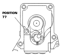
that the roller (position 77) is in its position. |
| 6. |
Reinstall housing cover ZL,
then reinstall hexagon socket shoulder screws with a drop
of Loctite* No. 222 on the thread of each screw. |
To Replace The Punch (Position 36)
| 1. |
Remove 2 cheese head machine
screws (position 35A) located on the underside of the
housing (position 58). |
| 2. |
Remove punch, clean area, replace
with new punch, then reinstall cheese head machine screws
with a drop of Loctite* No. 222 on the thread of each
screw. |
To Replace The Die (Position 18)
| 1. |
Remove housing cover ZL (position
66), by removing 3 hexagon socket shoulder screws (position
64) and 1 hexagon socket shoulder screw (position 63).
Important: This screw in position 63 must be reinstalled
in this exact position (lower left hand corner) as it
is shorter. It must also sit flush against the housing
cover ZL when reinstalled. |
| 2. |
Remove sealing lever (position
62), by loosening hexagon socket cap screw (position 61). |
| 3. |
Remove woodruff key (position
1). |
| 4. |
Remove eccentric shaft (position
72). |
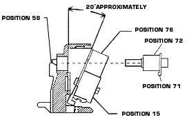
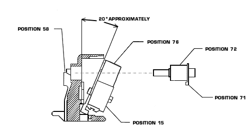
| 5. |
Remove the total internal assembly
by tilting it at a 20 degree angle (see diagram below)
and pull out with pliers by eccentric shaft plunger (position
76), at the same time making sure to hold internal assembly
together with other hand, exposing die on the underside
of the die and knife block (position 15). |
| 6. |
Remove 3 cheese head machine
screws (position 17). |
| 7. |
Remove die, clean area, and
replace with new die, then reinstall cheese head machine
screws with a drop of Loctite* No. 222 the thread of each
screw. |
| 8. |
To reinstall the internal assembly
follow the installation of internal assembly instructions
below. |
| 9. |
Reinstall the eccentric shaft
observing its relative position to the cam (position 45). |
| 10. |
The cam lever (position 71)
must engage with its tip into the cavity of the cam. The
components should align together and operate smoothly,
please do not force the parts together. |
| 11. |
Make certain that the area
is clean and well greased with white grease. |
| 12. |
Important: Make certain
that the roller (position 77) is in its position. |
| 13. |
Reinstall housing cover ZL,
then reinstall hexagon socket shoulder screws with a drop
of Loctite* No. 222 on the thread of each screw. |
| 14. |
Reinstall woodruff key and
sealing lever. |
| Removal of Internal Assembly ZL31 |
|
|
Installation of Internal Assembly ZL31
|
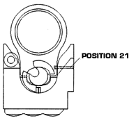
Figure 1A
Place the cam as per drawing, with the long width
sitting flat in the die and knife block. Add white
grease throughout. Then place the eccentric shaft
plunger on top of the cam and fasten by pushing the
connection pin, position 21 (making sure the groove
on this pin is facing the outside of the die and knife
block) through hole in die and knife block and into
like slot on eccentric shaft plunger.
|
|
|
Figure 1B
Tilt the internal assembly approximately 20 degrees
and place into housing making sure the back up hook
is sitting in its slot in the housing.
|
|
|
Figure 1C
Make sure the cam lever is attached to the eccentric
shaft. Then push it through the hole of eccentric
shaft plunger and the housing until it is flush.
|
|
|
Figure 1D
Turn the cam with pliers in a clockwise direction
until it sits in position shown in this drawing.
|
|
|
Figure 1E
Turn cam lever in a clockwise direction with fingers
until it sits in front of the cavity of the cam.
Important: Make certain that the roller (position
77) is in its position.
Then install the housing cover and the sealing lever
making sure they sit properly and operate smoothly,
do not force.
|
|
To Replace The Lower Cutter ZL31 (Position 55)
| 1. |
Remove cheese head machine screw (position 17A) located
on the underside of the housing (position 58). |
| 2. |
With small flat head screwdriver push out lower cutter
ZL31 from its position. |
| 3. |
Install and position new lower cutter ZL31 making
sure the thinner end faces toward outside of housing. |
| 4. |
Reinstall cheese head machine screw with a drop of
Loctite* No. 222 on the thread of each screw. |
To Replace the Punch ZL (Position 31)
| 1. |
Remove lever ZL (position 25) by loosening hexagon
socket cap screw (position 24). |
| 2. |
Remove woodruff key (position 29). |
| 3. |
Remove lock housing assembly ZL by removing 4 hexagon
socket cap screws (position 52) and 2 hexagon socket
cap screws (position 51). |
| 4. |
Remove lock housing cover ZL (position 34).
|
| 5. |
Remove open link ZL (position 50) and link pin (position
48). |
| 6. |
Remove punch ZL, replace with new punch ZL, then reinstall
link pin and open link ZL. |
| 7. |
Make certain that the area is clean and well greased
with white grease. Attach lock housing cover ZL. Then
reattach lock housing assembly ZL to front of housing
(position 58). |
To Replace The Compression Spring (Position 68) and
Ball (Position 67)
| 1. |
Remove housing cover ZL (position 66), by removing
3 hexagon socket shoulder screws (position 64) and 1
hexagon socket shoulder screw (position 63). Important:
This screw in position 63 must be reinstalled in this
exact position (lower left hand corner) as it is shorter.
It must also sit flush against the housing cover ZL
when reinstalled. |
| 2. |
Remove spring holder ZL (position 69) by removing
2 cheese head machine screws (position 17B) from the
inside of housing cover ZL. |
| 3. |
Remove compression spring, then ball and replace with
new in this order. |
| 4. |
Reinstall spring holder ZL to housing cover ZL with
cheese head machine screws and add a drop of Loctite*
No. 222 on the thread of each screw. |
| 5. |
Important: Make certain that the roller (position
77) is in its position. |
| 6. |
Reinstall housing cover ZL, then reinstall hexagon
socket shoulder screws with a drop of Loctite* No. 222
on the thread of each screw. |
| 7. |
Reinstall woodruff key and lever ZL. |
*Loctite is a registered trademark of the Loctite Corporation.
Top of page
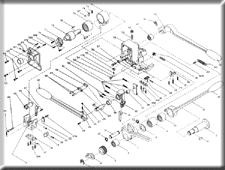
ZL31
DIAGRAM
|
|
This Diagram is available in a Portable Document Format
(PDF) file. To view it, you need to have Adobe Acrobat
Reader version 4.0 installed on your system. Acrobat
Reader is available as a free download from the Adobe
Acrobat Reader site.
These documents are fully printable and searchable.
For complete information on using Adobe Acrobat features,
including the option of downloading a free copy of Acrobat
Reader 4.0, go to the Adobe
Acrobat Reader site. |
Top of page
ZL31
PARTS LIST
|
Position
|
Part Number
|
Part Name
|
Parts per Tool
|
| 1,1A |
ZR-0001 |
Woodruff Key |
2
|
| 2 |
ZR-0002 |
Feedwheel Shaft |
1
|
| 3 |
ZR-0003 |
External Retaining Ring |
1
|
| 4 |
ZR-0006 |
Strap Guide 3/4" (19 mm) |
1
|
| 5 |
ZR-0074 |
Feedwheel 31 |
1
|
| 6 |
ZR-0008 |
Roller Bearing |
1
|
| 7 |
ZR-0009 |
Feedwheel Lever |
1
|
| 8 |
ZR-0010 |
Washer |
1
|
| 9 |
ZR-0011 |
Roller Clutch and Bearing Assembly |
1
|
| 10 |
ZR-0012 |
Roller Clutch |
1
|
| 11 |
ZR-0013 |
Tension Lever |
1
|
| 12 |
ZR-0014 |
Handle |
3
|
| 13 |
ZR-0025 |
External Retaining Ring |
2
|
| 14 |
ZR-0026 |
Shaft |
1
|
| 15 |
ZR-0067 |
Die and Knife Block 31 |
1
|
| 16 |
ZR-0016 |
Dowel Pin |
3
|
| 17, 17A, 17B |
ZR-0017 |
Cheese Head Machine Screw |
6
|
| 18 |
ZR-0068 |
Die 31 |
1
|
| 19 |
ZR-0069 |
Knife 31 (Includes ZR-0021) |
1
|
| 20 |
ZR-0021 |
Spring Tension Pin |
1
|
| 21 |
ZR-0022 |
Connection Pin |
1
|
| 22 |
ZR-0023 |
Back Up Hook |
1
|
| 23 |
ZR-0024 |
Spring Tension Pin |
2
|
| 24 |
ZR-0203 |
Hexagon Socket Cap Screw |
1
|
| 25 |
ZR-0200 |
Lever ZL |
1
|
| 26 |
ZR-0206 |
Hexagon Socket Set Screw |
1
|
| 27 |
ZR-0208 |
Nut |
1
|
| 28 |
ZR-0207 |
Eccentric Shaft ZL |
1
|
| 29 |
ZR-0213 |
Woodruff Key |
1
|
| 30 |
ZR-0214 |
Bronze Bushing |
1
|
| 31 |
ZR-0212 |
Punch ZL |
1
|
| 32 |
ZR-0209 |
Lock Housing ZL |
1
|
| 33 |
ZR-0215 |
Bronze Bushing |
1
|
| 34 |
ZR-0217 |
Lock Housing Cover ZL |
1
|
| 35, 35A |
ZR-0033 |
Cheese Head Machine Screw |
4
|
| 36 |
ZR-0071 |
Punch 31 |
1
|
| 37 |
ZR-0031 |
Gripper |
1
|
| 38, 38A |
ZR-0032 |
Spring Tension Pin |
2
|
| 39 |
ZR-0034 |
Spring Tension Pin |
2
|
| 40 |
ZR-0037 |
Strap Stop Front 3/4", 1 1/4"
(19mm, 32mm) |
1
|
| 41 |
ZR-0038 |
Hexagon Socket Set Screw |
1
|
| 42, 42A |
ZR-0039 |
Nut |
2
|
| 43 |
ZR-0040 |
Extension Spring |
1
|
| 44 |
ZR-0041 |
Hexagon Socket Cap Screw |
1
|
| 45 |
ZR-0042 |
Cam |
1
|
| 46 |
ZR-0045 |
Die Block Back Up |
1
|
| 47 |
ZR-0046 |
Spring Tension Pin |
1
|
| 48 |
ZR-0216 |
Link Pin |
2
|
| 49 |
ZR-0210 |
Closed Link ZL |
1
|
| 50 |
ZR-0211 |
Open Link ZL |
1
|
| 51 |
ZR-0220 |
Hexagon Socket Cap Screw |
2
|
| 52 |
ZR-0221 |
Hexagon Socket Cap Screw |
4
|
| 53 |
ZR-0047 |
Spacer |
1
|
| 54 |
ZR-0048 |
Pin |
1
|
| 55 |
ZR-0202 |
Lower Cutter ZL31 |
1
|
| 56 |
ZR-0051 |
Strap Stop Rear 3/4" (19mm) |
1
|
| 57 |
ZR-0052 |
Nut |
1
|
| 58 |
ZR-0219 |
Housing ZL31 |
1 |
| 59 |
ZR-0054 |
Hexagon Socket Set Screw |
1 |
| 60 |
ZR-0055 |
Roller Bearing |
1 |
| 61 |
ZR-0056 |
Hexagon Socket Cap Screw |
1 |
| 62 |
ZR-0057 |
Sealing Lever |
1 |
| 63 |
ZR-0223 |
Hexagon Socket Shoulder Screw |
1 |
| 64 |
ZR-0058 |
Hexagon Socket Shoulder Screw |
3 |
| 65 |
ZR-0059 |
Roller Bearing |
1 |
| 66 |
ZR-0204 |
Housing Cover ZL |
1 |
| 67 |
ZR-0043 |
Ball |
1 |
| 68 |
ZR-0224 |
Compression Spring |
1 |
| 69 |
ZR-0205 |
Spring Holder ZL |
1 |
| 70 |
ZR-0061 |
Cheese Head Machine Screw |
2 |
| 71 |
ZR-0078 |
Cam Lever |
1 |
| 72 |
ZR-0063A |
Eccentric Shaft 31 |
1 |
| 73 |
ZR-0064 |
Roller Bearing |
1 |
| 74 |
ZR-0044 |
Compression Spring |
1 |
| 75 |
ZR-0075 |
Spring Tension Pin |
1 |
| 76 |
ZR-0065 |
Eccentric Shaft Plunger
(Includes ZR-0043, ZR-0044, ZR-0064, ZR-0075) |
1 |
| 77 |
ZR-0076 |
Roller |
1
|
| 78 |
ZR-0077 |
Roller Pin |
1
|
| 79 |
ZR-0028 |
Dowel Pin |
1
|
| -- |
ZR-0226 |
Operation Manual and Parts List for ZL31
Series Tools. |
1 |
Top of page
Click here for Trade
Sheet Back
Email Us
ZR Tool - Strapping Machines & Strapping Tools
|
|